
Demonstration manual for the Linear Technology LTM4618EV step‑down µModule regulator and its DC1472A demo board.
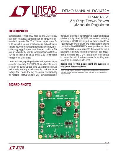
The DC1472A demonstration circuit showcases the LTM4618EV 6 A step‑down power µModule regulator. It operates from 4.5 V to 26.5 V input and provides jumper‑selectable output voltages from 0.8 V to 5 V. The board includes a simple layout with bulk input and output capacitors, a TRACK/SS pin for voltage ramp control, and a RUN pin for enable/disable.
The manual contains a quick‑start procedure, performance summary, parts list, schematic diagram, and safety notices. It is intended for engineering development and evaluation, not for commercial product use.
| Input Voltage Range | 4.5 V to 26.5 V |
|---|---|
| Maximum Continuous Output Current | 6 A |
| Default Switching Frequency | 500 kHz |
| External Clock Sync Range | 250 kHz to 750 kHz |
| Package Size | 9 mm × 15 mm × 4.32 mm LGA |
The board operates from 4.5 V up to 26.5 V input.
Place the jumpers as shown for the 5 V setting (JP6, JP3, JP4, JP2) and then repeat the power‑on steps.
It can deliver up to 6 A of continuous output current, subject to derating under certain conditions.
The default switching frequency is 500 kHz.