
This Linear Technology manual describes the DC2091A evaluation board for the LTC5599 low‑power direct quadrature modulator, with setup, test procedures, and…
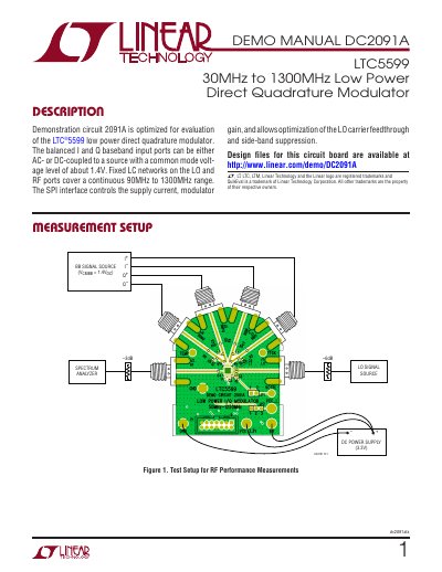
The DC2091A demonstration board is designed to evaluate the LTC5599 low‑power direct quadrature modulator. It provides balanced I/Q baseband inputs, fixed LC networks covering 90 MHz‑1300 MHz, and an SPI interface for control. The manual includes a description of the circuit, recommended test equipment, and detailed wiring diagrams.
Key sections cover test‑equipment setup, a quick‑start procedure for powering up the board, measurement steps for gain, compression point, image rejection and LO leakage, the full schematic, a complete parts list, and safety/warranty notices. The document also points to design files available on Linear Technology’s website.
| Supply Voltage | 3.3 V (do not exceed 3.8 V) |
|---|---|
| Typical Supply Current | ≈28 mA |
| Input Voltage Range (any pin) | –0.3 V to VCC + 0.3 V |
| Operating Temperature Range | –40 °C to 105 °C |
| Storage Temperature Range | –65 °C to 150 °C |
| LOL/LOC DC Voltage (absolute max) | ±0.1 V |
Set the supply voltage to 3.3 V and do not exceed 3.8 V.
The total VCC supply current is approximately 28 mA.
It operates from –40 °C to 105 °C.