
The Linear Technology DC1884A Demo Manual provides setup, jumper settings, power and signal instructions, and software usage for the ADC demonstration board.
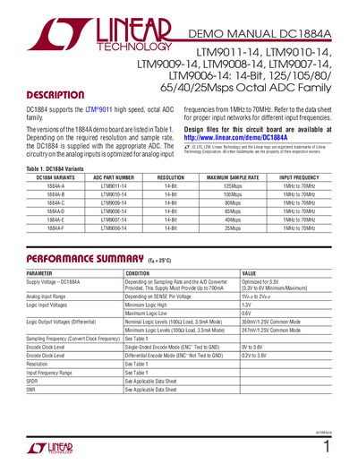
The DC1884A demo board is designed to evaluate the LTM9011‑14 family of 14‑bit octal ADCs. It includes default jumper configurations, power requirements, and guidance on analog input networks, encode clock, and digital output connections. The board operates from a 3.3 V to 6 V supply and may draw up to 700 mA depending on the selected ADC and sampling rate.
Software control is provided by the PScope system, which can program the board serially and configure options such as randomizer, two's complement mode, sleep mode, and LVDS output current. The manual also contains safety notices and warranty information for engineering development use only.
| Supply Voltage | 3.3 V–6 V (optimized for 3.5 V), up to 700 mA |
|---|---|
| Maximum Sample Rate (LTM9011‑14) | 125 Msps |
| Input Frequency Range | 1 MHz–70 MHz |
| Encode Clock Level (Single‑Ended) | 0 V–3.6 V |
The board operates from 3.3 V to 6 V, optimized for 3.5 V, and may draw up to 700 mA depending on the ADC and sample rate.
Set jumper JP14 to PAR/SER; the default position is Serial.
The LTM9011‑14 provides a maximum sample rate of 125 Msps.
The board is controlled by the PScope system software, which can be launched from the Linear Technology website.