
This document is the Allied Telesis AT-IE200 Series Industrial Ethernet Switches Installation Guide
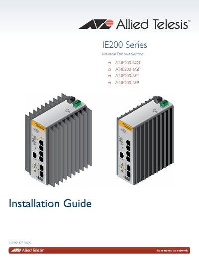
This guide provides step-by-step instructions for installing Allied Telesis AT-IE200 Series industrial Ethernet switches. It covers site selection, mounting on DIN rails or walls, cabling twisted pair and SFP ports, powering the device, and starting management sessions via local, Telnet, SSH, or web browser methods. Technical specifications and port pinouts are included in the appendix.
| Models | AT-IE200-6GT, AT-IE200-6GP, AT-IE200-6FT, AT-IE200-6FP |
|---|---|
| Console Port Pinout | Pin 1: Open, Pin 2: Receive Data, Pin 3: Ground, Pin 4: Ground, Pin 5: Transmit Data, Pin 6: Loop to pin 7 |
The series includes AT-IE200-6GT, AT-IE200-6GP, AT-IE200-6FT, and AT-IE200-6FP.
Pin 1 is open, Pin 2 is receive data, Pin 3 and 4 are ground, Pin 5 is transmit data, and Pin 6 is looped to pin 7.