
This document describes the features and usage of the SSI module in moog MSD Servo Drive
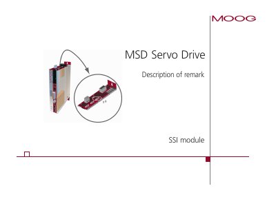
The MSD Servo Drive features an SSI Encoder Simulation function that allows a higher-level control system to read the current actual position of the drive. This feature utilizes the technology board slot (X8) and automatically detects the technology board when present.
The document provides detailed information on enabling the simulation, configuring parameters such as multi-turn and single-turn bits, polarity, phase, parity, and synchronization. It also includes a pin assignment table for the SSI Encoder Simulation interface.
| Clock rates supported | 200 kBit/s to 1500 kBit/s |
|---|---|
| Fastest possible cycle time | 125 ps |
| Encoder monoflop time | ~25 ps |
| Total information bits transferable | 32 bits |
SSI Encoder Simulation is enabled by setting parameter TOPT_SSI_EncSimEnable (P 2800) to 1.
The system supports clock rates between 200 kBit/s and 1500 kBit/s.
Yes, an optional parity bit can be transferred after the least significant bit (LSB) using parameters TOPT_SSI_ParityEnable and TOPT_SSI_ParityType.