
These Application Notes are a guide to applying the G122-829-001 P-I Servoamplifier. They can be used to determine the closed loop structure for the application, select the G122-829-001, determine the system configuration, draw the wiring diagram, and install and commission the system.
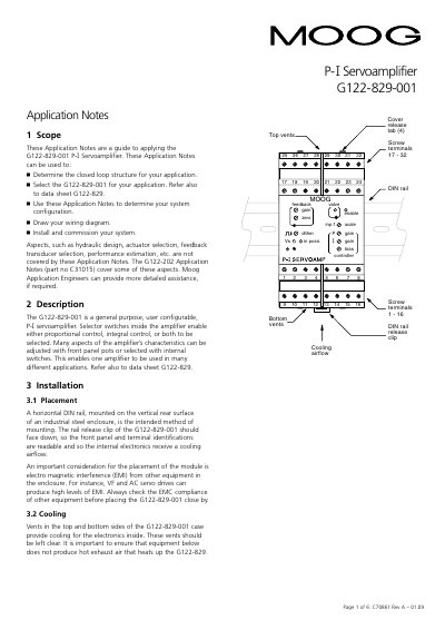
This document serves as a guide for applying the G122-829-001 P-Iservoamplifier, assisting users in determining closed-loop structures, selecting the amplifier, and configuring system settings. It provides instructions for drawing wiring diagrams, installing the unit on a DIN rail, and commissioning the system, while noting that hydraulic design and actuator selection are not covered.
| Power supply voltage | 24V DC nominal |
|---|---|
| Power consumption (no load) | 75mA @ 24V |
| Power consumption (100mA load) | 200mA |
| Recommended fuse | M205, 250mA T |
| Wire size range | 0.2mm2 to 2.5mm2 |
| Input 1 scale range | 10 to 100% |
| Input 1 lag option | 55mS |
| Output voltage range | ±10V |
| Output current range | ±5 to ±100mA |
| Maximum load resistance (50mA) | 181 Ohm |
An M205, 250mA T (slow blow) fuse compliant with IEC127-2 sheet 3 is recommended.
The terminals accommodate wire sizes from 0.2mm2 to 2.5mm2 (24AWG to 12AWG).
It should be mounted on a horizontal DIN rail on the vertical rear surface of an industrial steel enclosure.
The default setup is 4-20mA flowing into terminal 18 and out of terminal 17, producing an output of 0 to -10V.