
The MCR225FP/D is a reverse blocking thyristor designed primarily for half-wave ac control applications such as motor controls, heating controls and power supply crowbar circuits. The thyristor has the following features: Glass passivated junctions with center gate fire for greater parameter uniformity and stability; Small, rugged, Thermowatt constructed for low thermal resistance, high heat dissipation and durability; Blocking voltage to 800 volts; 300 A surge current capability; Insulated package simplifies mounting.
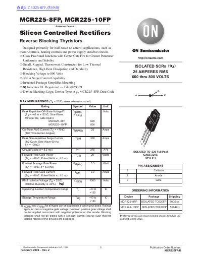
This datasheet describes the MCR225-8FP and MCR225-10FP, which are silicon controlled rectifiers (SCRs) and reverse blocking thyristors designed primarily for half-wave AC control applications. These devices are suitable for motor controls, heating controls, and power supply crowbar circuits. They feature glass passivated junctions with a center gate fire for greater parameter uniformity and stability.
| Peak Repetitive Off-State Voltage (MCR225-8FP) | 600 Volts |
|---|---|
| Peak Repetitive Off-State Voltage (MCR225-10FP) | 800 Volts |
| On-State RMS Current | 25 Amps |
| Peak Non-repetitive Surge Current | 300 Amps |
| Operating Junction Temperature Range | -40 to +125°C |
| Thermal Resistance, Junction to Case | 1.5°C/W |
| Package Style | ISOLATED TO-220 Full Pack |
They are designed primarily for half-wave AC control applications, such as motor controls, heating controls and power supply crowbar circuits.
The maximum lead temperature for soldering purposes is 260°C for 1/8” from the case for 10 seconds.