
This document describes a reverse blocking thyristor designed primarily for half-wave AC control applications, such as motor controls, heating controls, and power supply crowbar circuits. It features glass passivated junctions, small and rugged construction for low thermal resistance, high heat dissipation, and durability.
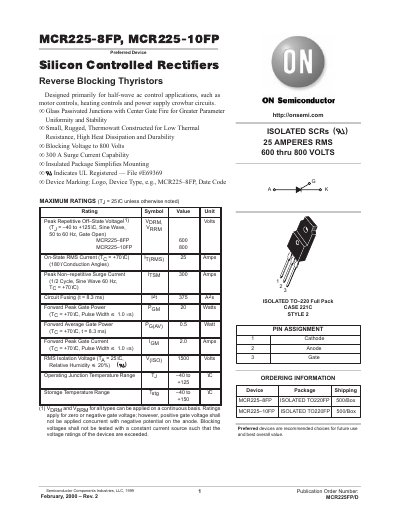
This datasheet describes the MCR225-8FP and MCR225-10FP, which are silicon controlled rectifiers (SCRs) designed primarily for half-wave AC control applications such as motor controls, heating controls, and power supply crowbar circuits. These devices feature glass passivated junctions with center gate fire for greater parameter uniformity and stability, housed in an insulated TO-220 full pack package to simplify mounting.
| Peak Repetitive Off-State Voltage (VDRM) | 600 Volts (MCR225-8FP) |
|---|---|
| Peak Repetitive Off-State Voltage (VRRM) | 800 Volts (MCR225-10FP) |
| On-State RMS Current (IT(RMS)) | 25 Amps |
| Peak Non-repetitive Surge Current (ITSM) | 300 Amps |
| Thermal Resistance, Junction to Case (RthJC) | 1.5 °C/W |
| Operating Junction Temperature Range | -40 to +125 °C |
| RMS Isolation Voltage | 1500 Volts |
They are designed primarily for half-wave AC control applications, such as motor controls, heating controls and power supply crowbar circuits.
The devices are housed in an insulated TO-220 full pack package.
The maximum lead temperature is 260 °C for 1/8" from the case for 10 seconds.