
STMicroelectronics AN440 Application Note

This document describes a trigger circuit for triggering the TRIAC in the second and third quadrants in a system using a positive power supply. New series TRIACs can replace conventional TRIACs by simply adding a capacitor and a diode.
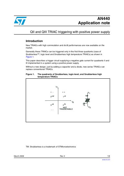

STMicroelectronics AN440 Application Note - cover page
Brand
STMicroelectronics
Category
Triac
Document type
Application Note
Language
English
Pages
8
File format
PDF
File size
101 KB
Published
06 August, 2012
Updated
29 September, 2023
Model
440A
MD5 checksum
6B6182BA1533427DF3D9C14632C8F41D

About this manual

This document details a method to trigger TRIACs in the second and third quadrants (QII and QIII) using a positive power supply. The proposed circuit utilizes a discharge capacitor and a diode to generate a negative gate current pulse required for triggering these specific quadrants.

What's inside

  • Introduction
  • Principle of proposed gate circuit
  • Gate current pulse width setting
  • Experimental results
  • Conclusion

Frequently asked questions

What is the minimum gate current pulse width required for this circuit?

The circuit requires a minimum gate current pulse width of 20 us to ensure proper triggering.

What is the maximum latching current for most CW Snubberless TRIACs in quadrants Q1 through Q3?

The maximum latching current is 50 mA for these specific TRIACs and quadrants.

What happens if a logic or transistor failure occurs in this trigger circuit?

The capacitor acts as an open circuit for dc current, which avoids all triggering.

Download PDF (101 KB)

More STMicroelectronics Manuals


View all STMicroelectronics manuals →