
This is an application note that describes how to design a power factor correction circuit using FAN7529
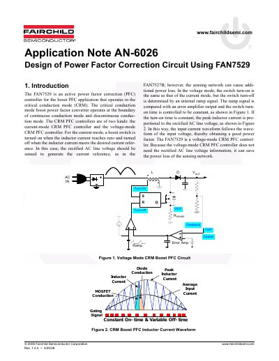
The document describes the FAN7529 as a voltage-mode critical conduction mode (CRM) power factor correction (PFC) controller for boost applications. It explains the operating principles of voltage-mode CRM PFC controllers, highlighting how they achieve good power factor by controlling the switch turn-on time to be constant, which makes the peak inductor current proportional to the rectified AC line voltage. This approach eliminates the need for sensing the rectified AC line voltage, thereby saving power loss associated with sensing networks.
The note provides a detailed block diagram and description of the FAN7529's internal architecture, including the error amplifier, zero current detector, sawtooth generator, over-current protection, and switch drive blocks. It further outlines the design procedures for key circuit components, such as the boost inductor, auxiliary winding, and input capacitor, providing relevant equations and design considerations to ensure optimal performance and minimize total harmonic distortion (THD).
| Operating Mode | Voltage-mode Critical Conduction Mode (CRM) |
|---|---|
| Application Type | Boost PFC application |
| OVP Comparator Threshold | 2.675V |
| Disable Comparator Threshold | 0.45V |
| ZCD Turn-on Threshold | 1.4V |
| MOT Pin Voltage | 2.9V |
| Drive Output Sourcing Current | 500mA peak |
| Drive Output Sinking Current | 800mA peak |
| Output Voltage Clamp | 13V |
| Over-Current Protection Threshold | 0.8V |
The FAN7529 is a voltage-mode critical conduction mode (CRM) PFC controller.
The MOSFET turn-on time is determined by an internal ramp signal compared with an error amplifier output.
The ZCD generates the turn-on signal of the MOSFET when the boost inductor current reaches zero.