
This application note introduces the FAN7527B's features and characteristics, including the internal circuit structure, working principle and application circuits.
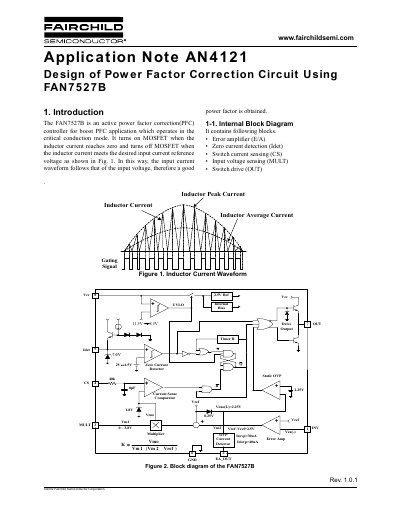
The document describes the FAN7527B, an active power factor correction (PFC) controller designed for boost PFC applications operating in critical conduction mode. It ensures the input current waveform follows the input voltage to achieve a good power factor by turning on the MOSFET when inductor current reaches zero and turning it off based on a reference voltage.
The note details the internal block diagram and functions, including the error amplifier, zero current detection, switch current sensing, input voltage sensing, and switch drive. It also provides design equations and guidelines for the power stage, auxiliary winding, and input capacitor.
| Operating Mode | Critical conduction mode |
|---|---|
| Application Type | Boost PFC application |
| Control Loop Bandwidth | Below 20Hz |
| Soft OVP Threshold | 30uA |
| Dynamic OVP Threshold | 40uA |
| Quiescent Current (OVP) | 2mA |
| Static OVP Threshold | 2.25V |
| Drive Output Peak Current | 500mA |
| Drive Output Rise Time | 130ns |
| Drive Output Fall Time | 50ns |
| Zero Current Detector Threshold | 1.5V |
| Zero Current Detector Hysteresis | 0.5V |
| Watchdog Timer Delay | 150us |
The FAN7527B operates in the critical conduction mode.
It turns on the MOSFET when the inductor current reaches zero and turns it off when the current meets the desired input current reference voltage.
The maximum peak switch current is limited to 1.8V divided by the sense resistor (Rsense).
No, an internal watchdog timer function eliminates the need for an external oscillator in stand-alone applications.