
This application note describes a power factor correction (PFC) circuit design using the FAN7530. The circuit operates in the critical conduction mode (CRM).
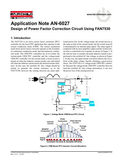
The document introduces the FAN7530, an active power factor correction (PFC) controller designed for boost PFC applications operating in critical conduction mode (CRM). It explains that this voltage-mode controller does not require sensing the rectified AC line voltage, which reduces power loss in the sensing network compared to current-mode controllers.
| Operating Mode | Voltage-mode CRM PFC controller |
|---|---|
| Drive Output Sourcing Current | 500mA peak |
| Drive Output Sinking Current | 800mA peak |
| Drive Output Rise/Fall Time | 50ns |
| Drive Output Clamping Voltage | 13V |
| OVP Comparator Threshold | 2.675V |
| Disable Comparator Threshold | 0.45V |
| OCP Comparator Threshold | 0.8V |
| Minimum Timer Duration | 150µs |
It does not need to detect the rectified AC line voltage, which reduces power loss in the sensing network.
It is determined by comparing the output of the error amplifier with the output of the sawtooth generator.
The over-voltage protection comparator shuts down the output drive block.