
This application note illustrates how to interface RF I/Q modulators with several popular D/A converters, and introduces the circuits required for the interface to maximize voltage transfer from the DAC to the baseband inputs of the modulator, as well as provide some reconstruction filtering.
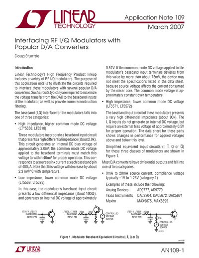
The document explains how to interface Linear Technology's High Frequency Product lineup of RF I/Q modulators with several popular D/A converters. It details the specific baseband input circuit categories for different modulator models (LT5571, LT5572, LT5558, LT5518, LT5568, and LT5528) and their required common mode DC voltages.
The note describes three passive networks used to couple D/A converter outputs to modulator inputs: direct coupling, transformer coupling, and voltage shift networks. It provides example circuits for interfacing Category 1 and Category 2 DACs (from manufacturers like Analog Devices, Texas Instruments, and Maxim) with these modulators, including considerations for carrier suppression and sidetone suppression.
The three categories are: high impedance with higher common mode DC voltage, high impedance with lower common mode DC voltage, and low impedance with lower common mode DC voltage.
These circuits generate an internal DC bias voltage of approximately 2.06V.