
The ADXL202EB is a simple evaluation board that allows the user to quickly evaluate the performance of the ADXL202 dual axis ±2 g accelerometer. Only three additional through-hole passive components must be added, depending on the bandwidth required in your application.
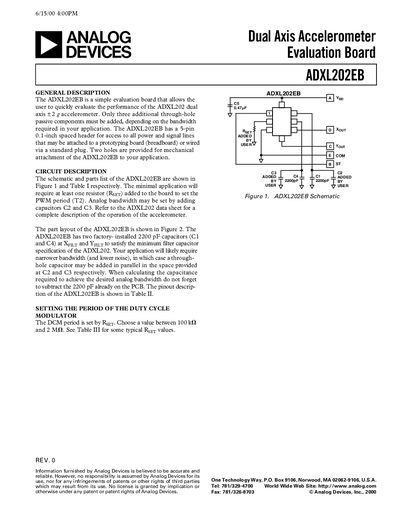
The ADXL202EB is a simple evaluation board that lets users quickly evaluate the ADXL202 dual‑axis +2 g accelerometer. It provides a 5‑pin header for power and signal connections and two mounting holes for mechanical attachment.
The document covers the circuit description, parts list, pinout, PWM period setting, bandwidth selection, and handling notes. It includes tables with resistor values for PWM periods, typical capacitor values for bandwidth, and safety warnings about reverse polarity and shock exposure.
| Supply voltage | 3 to 5.25 VDC |
|---|---|
| PWM period values | 1 ms @ 124 kΩ, 2 ms @ 248 kΩ, 5 ms @ 620 kΩ, 10 ms @ 1.24 MΩ |
| Default filter capacitors | 2200 pF on Xp and Ypr pins |
The board operates from a +V supply of 3 V to 5.25 V DC.
The PWM period is set by resistor Rgyr; typical values are listed in Table II (e.g., 124 kΩ gives 1 ms).
No, the ADXL202EB is not reverse‑polarity protected; reversing +V and ground will damage it.