
TLP1004A(F) and TLP1005A(F) are digital output photo-interrupters combining GaAs infrared LED with high sensitive and high gain Si photo IC. They are suitable for home electric equipment such as VCR, CD player, OA equipment such as copying machine, printer, facsimile, etc., and automatic service equipment such as vending machine, various position detection. The products can be directly connected to TTL, LSTTL, and CMOS, and can be directly mounted on a printed wiring board. The gap is 3mm and the resolution is 0.5mm. TLP1004A(F) has a low-level output at shielding, and TLP1005A(F) has a high-level output at shielding. The product has a built-in Schmitt circuit, a threshold input current of 4mA (max.) at Ta = 25°C, an operating supply voltage of VCC = 4.5V~17V, and high-speed response. The detector side is of visible light cut type.
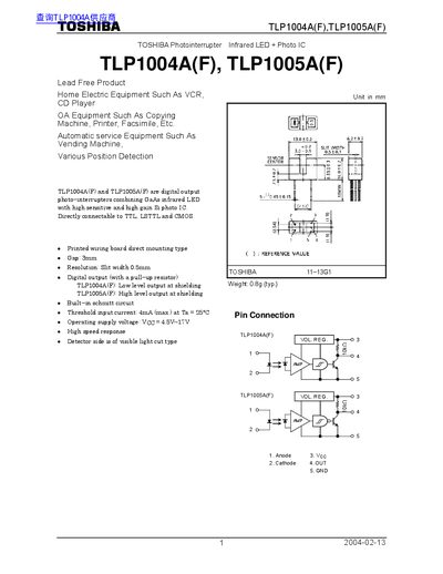
The Toshiba TLP1004A(F) and TLP1005A(F) are digital‑output photointerrupters that combine a GaAs infrared LED with a high‑gain Si photo‑IC. They are designed for direct connection to TTL, LSTTL and CMOS logic and feature a 3 mm gap and 0.5 mm slit width.
Key specifications include a forward current rating of 50 mA, a supply voltage range of 4.5 V to 17 V, and an operating temperature range of –25 °C to 85 °C. The devices incorporate built‑in Schmitt trigger circuits, provide low‑level (TLP1004A) or high‑level (TLP1005A) outputs, and include recommended precautions for soldering and handling of the polycarbonate package.
| Forward current (IF) max | 50 mA |
|---|---|
| Supply voltage (VCC) range | 4.5 V – 17 V |
| Operating temperature range | ‑25 °C to 85 °C |
| Gap between emitter and detector | 3 mm |
| Slit width (resolution) | 0.5 mm |
| Low‑level output current (IOL) | 16 mA |
The maximum forward current is 50 mA.
The devices operate with a supply voltage between 4.5 V and 17 V.
Soldering should be performed after lead forming.
The recommended gap is 3 mm.