
This document describes the features and characteristics of the SCES337G model. The product supports 2V to 5.5V VCC operation and has low output ground bounce and high output VOH undershoot. The outputs are disabled during power up and power down with inputs tied to VCC. The product supports mixed-mode voltage operation on all ports and has latch-up performance exceeding 100mA and ESD protection exceeding 2000V.
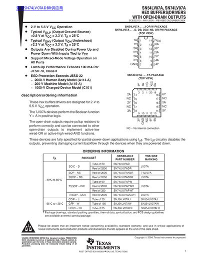
The SN54LV07A and SN74LV07A are hex buffers/drivers that provide open‑drain outputs. They operate from 2 V to 5.5 V supply voltage, support mixed‑mode voltage operation, and feature ESD protection up to 2000 V HBM. The devices require external pull‑up resistors for proper operation and have disabled outputs during power‑up and power‑down to prevent back‑flow current.
The data sheet includes detailed electrical characteristics, switching and noise specifications, recommended operating conditions, and mechanical drawings for several surface‑mount packages (SOIC, SOP, SSOP, PW, etc.). Ordering information, package drawings, and TI's standard warranty notice are also provided.
| Continuous output current | 35 mA |
|---|---|
| Operating temperature range | -40 °C to 125 °C |
| Package thermal impedance (DB) | 96 °C/W |
Yes, the open‑drain outputs require pull‑up resistors to Vcc for correct operation.
No, the outputs are disabled during power‑up and power‑down to prevent damaging current backflow.