
SLLS177G is a programmable auto-RTS and auto-CTS device with multiple modes and features. It supports CTS control of the transmitter and RTS control of the RCV FIFO contents and threshold. It can directly drive an RJ11 cable and is compatible with existing TL16C450 software. The device operates at high clock rates and has a programmable baud rate generator for high-speed operation. It also features complete status reporting capabilities and programmable serial interface characteristics.
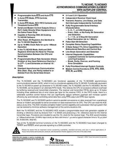
The TL16C550C and TL16C550CI are asynchronous communications elements with autoflow control, offering programmable auto‑RTS and auto‑CTS to reduce software overhead. They are compatible with TL16C450 software, feature up to a 16 MHz clock for 1 Mbaud operation, and include 16‑byte transmit and receive FIFOs with error‑status bits.
The document details functional block diagrams, terminal functions, absolute maximum ratings, recommended operating conditions for 3.3 V and 5 V supplies, mechanical package data (N‑package and PT‑S‑PQFP‑G48), and an important notice on product warranties and revisions.
| Maximum Clock Rate | 16 MHz (up to 1 Mbaud) |
|---|---|
| FIFO Depth | 16 bytes (per transmit and receive FIFO) |
| Supply Voltage Range (low‑voltage version) | 3.0 V – 3.6 V |
| Supply Voltage Range (standard version) | 4.75 V – 5.25 V |
| Operating Temperature Range (TL16C550CI) | -40 °C – 85 °C |
Autoflow control combines auto‑CTS and auto‑RTS to automatically manage serial data flow, reducing interrupt load and preventing overrun errors.
A programmable baud‑rate generator divides any input reference clock by 1 to 65 535 and provides a 16× clock for the transmitter and receiver.
The device operates from a low‑voltage supply of 3.0 V – 3.6 V or a standard 5 V supply of 4.75 V – 5.25 V, with corresponding input and output voltage ranges.