
This datasheet lists the specifications of the SN74LVC2G74 single positive-edge triggered D-type flip-flop, including package type, package size, input voltage range, output voltage range, output drive capability, power consumption, etc.
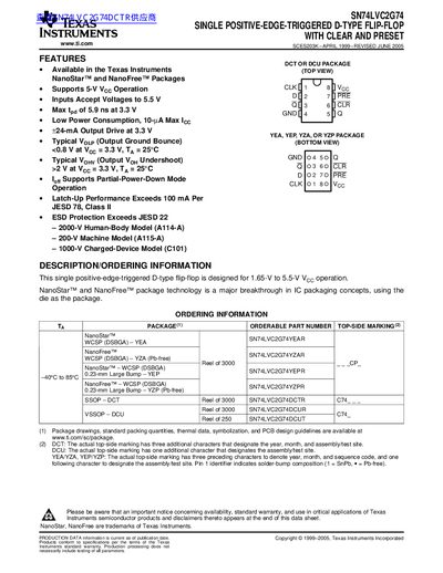
The SN74LVC2G74 is a single positive‑edge‑triggered D‑type flip‑flop designed for 1.65 V to 5.5 V operation and supports clear (CLR) and preset (PRE) inputs. It is offered in NanoStar™ and NanoFree™ package technologies, which integrate the die as the package.
The document provides ordering information, electrical specifications, absolute maximum ratings, recommended operating conditions, and detailed package options, along with mechanical drawings and legal notices.
| Recommended supply voltage range | 1.65 V to 5.5 V |
|---|---|
| Absolute maximum supply voltage | -0.5 V to 6.5 V |
| Maximum output drive current | 24 mA at 3.3 V |
| Low‑power consumption (Icc max) | 10 µA |
The device is specified to operate with a supply voltage between 1.65 V and 5.5 V.
The flip‑flop can source up to 24 mA when powered at 3.3 V.