
The MAX3054/MAX3055/MAX3056 are interfaces between the protocol controller and the physical wires of the bus lines in a controller area network (CAN). The devices provide differential transmit capability and switch to single-wire mode if certain fault conditions occur. The MAX3054/MAX3055/MAX3056 guarantee full wake-up capability during failure modes. The extended fault-protected voltage range of CANH and CANL bus lines of ±80V allows for use in 42V automotive applications. Current-limiting and thermal- protection circuits protect the transmitter output stage against overcurrent faults to prevent destruction of the transmitter output stage. The CANH and CANL lines are also protected against electrical transients that may occur in an automotive environment. The transceiver provides three low-power modes that can be entered and exited through pins STB and EN. An output INH pin can be used for deactivation of an external voltage regulator. The MAX3054/MAX3055/MAX3056 are designed to pro- vide optimal operation for a specified data rate. The MAX3054 is ideal for high data rates of 250kbps. The MAX3055 is used for data rates of 125kbps and the MAX3056 is designed for 40kbps applications. For the 40kbps and 125kbps versions, a built-in slope-control feature allows the use of unshielded cables, and receiv- er input filters guarantee high noise immunity. Applications Automotive Features o Pin and Functionally Compatible with TJA1054 o ±80V Fault Protection Suitabl
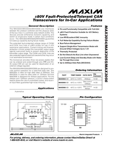
The MAX3054, MAX3055 and MAX3056 are +80 V fault‑protected CAN transceivers designed for in‑car applications. They provide differential transmit capability, automatic single‑wire mode on fault, and full wake‑up functionality. The devices support low‑power standby modes controlled by the STB and EN pins, with an INH pin for external regulator deactivation.
Key features include high voltage tolerance (+80 V on CANH/CANL), low RFI/EMC performance, bus‑failure management, and data‑rate specific variants: up to 250 kbps (MAX3054), 125 kbps (MAX3055) and 40 kbps (MAX3056). The datasheet provides absolute maximum ratings, DC/AC electrical characteristics, timing diagrams, and package dimensions.
| Maximum CAN bus line voltage | +80 V |
|---|---|
| Operating temperature range | -40 °C to +125 °C |
The transceivers are rated for a fault‑protected voltage of up to +80 V on the CANH and CANL bus lines.
Low‑power modes are controlled through the STB and EN pins; the INH pin can deactivate an external voltage regulator.
A 0.1 µF ceramic capacitor should be placed close to the IC with short leads and wide trace widths.