
This document provides preliminary information on a new product, the ST52F510/F513/F514 8-bit Intelligent Controller Unit (ICU). The product features two Timer/PWMs, ADC, I2C, SPI, SCI, memories, core, clock and power supply, interrupts, I/O ports, and peripherals.
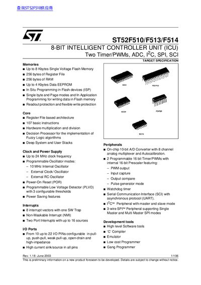
This handbook describes the ST52F510/F513/F514 family of 8‑bit Intelligent Controller Units (ICU). It covers the device architecture, memory organization, fuzzy‑logic capabilities, and the full set of on‑chip peripherals such as timers, PWM, ADC, SCI, I²C and SPI.
The document explains programming options including In‑Situ Programming (ISP) and In‑Application Programming (IAP), power‑saving modes, interrupt handling, and detailed register maps for each peripheral, enabling developers to integrate the microcontroller into a wide range of applications.
| CPU architecture | 8‑bit Intelligent Controller Unit (ICU) |
|---|---|
| Peripherals | Two Timer/PWMs, ADC, 2‑wire SPI, SCI |
| Flash memory | Up to 8 Kbytes Single Voltage Flash |
| Register file | 256 bytes |
| RAM | 256 bytes |
| Data EEPROM | Up to 4 Kbytes |
| Maximum clock frequency | 24 MHz |
| Oscillator options | 10 MHz internal, external clock/oscillator, external RC |
| Interrupt vectors | 8 vectors (plus one SW trap) |
| I/O pins | 10 to 22 configurable pins |
| A/D converter | 10‑bit, 8‑channel analog multiplexer |
| Instruction set | 107 basic instructions |
The device provides up to 8 Kbytes of single‑voltage flash memory.
It includes 8 interrupt vectors plus one software trap.
The ICU can run up to 24 MHz and offers a 10 MHz internal oscillator, an external clock/oscillator, and an external RC oscillator.
Between 10 and 22 I/O pins are configurable in various modes.