
The DRV593 and DRV594 are high-efficiency, high-current power amplifiers ideal for driving a wide variety of thermoelectric cooler elements in systems powered from 2.8 V to 5.5 V. The operation of the device requires only one inductor and capacitor for the output filter, saving significant printed-circuit board area. Pulse-width modulation (PWM) operation and low output stage on-resistance significantly decrease power dissipation in the amplifier. The DRV593 and DRV594 are internally protected against thermal and current overloads. Logic-level fault indicators signal when the junction temperature has reached approximately 115°C to allow for system-level shutdown before the amplifier’s internal thermal shutdown circuitry activates. The fault indicators also signal when an overcurrent event has occurred. If the overcurrent circuitry is tripped, the device will perform a system-level shutdown.
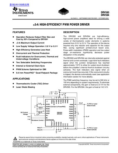
The DRV593 and DRV594 are high‑efficiency, high‑current PWM power drivers designed for thermoelectric cooler (TEC) and laser diode applications. They operate from 2.8 V to 5.5 V and require only a single inductor and capacitor for the output filter, reducing board space.
Both devices include internal overcurrent, thermal, and undervoltage protection with fault indicators, selectable switching frequencies (500 kHz or 100 kHz), and fixed voltage gains (2.3 V/V for DRV593, 14.5 V/V for DRV594). The package is a 9 mm × 9 mm PowerPAD™ Quad Flatpack.
| Maximum continuous output current | 3 A |
|---|---|
| DRV593 voltage gain | 2.3 V/V |
| Selectable switching frequency | 500 kHz or 100 kHz |
| Package type | PowerPAD™ Quad Flatpack (9 mm × 9 mm) |
Apply a TTL logic low to the FREQ pin for 500 kHz or a TTL logic high for 100 kHz.
Both the DRV593 and DRV594 can deliver up to 3 A continuously.
They include overcurrent, thermal, and undervoltage fault indicators that signal fault conditions.