
MAX7462/MAX7463 are single-channel, standard-definition, integrated video reconstruction filters and buffers that are ideal for anti-aliasing and digital-to-analog smoothing video applications or wherever analog video is reconstructed from digital data (such as cable/satellite/terrestrial set-top boxes and DVRs).
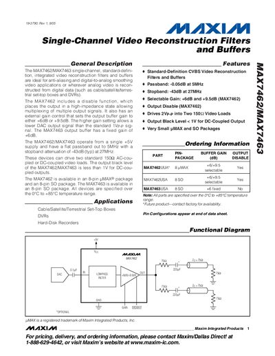
The MAX7462 and MAX7463 are integrated video reconstruction filters and buffers designed for standard‑definition CVBS video applications such as set‑top boxes, DVRs and hard‑disk recorders. They operate from a single +5 V supply and provide a flat passband to 5 MHz with a stopband attenuation of -43 dB at 27 MHz.
Key features include selectable gain (+6 dB or +9.5 dB) for the MAX7462, a fixed +6 dB gain for the MAX7463, an output‑disable pin on the MAX7462, and the ability to drive two 150 Ω video loads with an output black level below 1 V. The devices are offered in 8‑pin UMAX and 8‑pin SO packages and are specified over a temperature range of 0 °C to +85 °C.
| Passband | -0.05 dB at 5 MHz |
|---|---|
| Stopband Attenuation | -43 dB at 27 MHz |
| Gain (MAX7462) | Selectable +6 dB / +9.5 dB |
| Output Disable | Yes (MAX7462) |
| Supply Current (no load) | 25‑35 mA |
| Package Types | 8‑pin UMAX, 8‑pin SO |
Both devices operate from a single +5 V supply.
Yes, the MAX7462 includes an output‑disable pin that places the output in a high‑impedance state.