
The MAX1205 is a 14-bit monolithic analog-to-digital converter (ADC) capable of conversion rates up to 1Msps. This integrated circuit, built on a CMOS pro- cess, uses a fully differential, pipelined architecture with digital error correction and a short self-calibration procedure that corrects for capacitor and gain mis- matches and ensures 14-bit linearity at full sample rates. An on-chip track/hold (T/H) maintains superb dynamic performance up to the Nyquist frequency. The MAX1205 operates from a single +5V supply. The fully differential inputs allow an input swing of ±VREF. The reference is also differential, with the posi- tive reference (RFPF) typically connected to +4.096V and the negative reference (RFNF) connected to ana- log ground. Additional sensing pins (RFPS, RFNS) are provided to compensate for any resistive-divider action that may occur due to finite internal and external resis- tances in the reference traces and the on-chip resis- tance of the reference pins. A single-ended input is also possible using two operational amplifiers. The power dissipation is typically 257mW at +5V, at a sampling rate of 1Msps. The device employs a CMOS- compatible, 14-bit parallel, two’s complement output data format. For higher sampling rates, the MAX1201 is a 2.2Msps pin-compatible upgrade to the MAX1205. The MAX1205 is availab
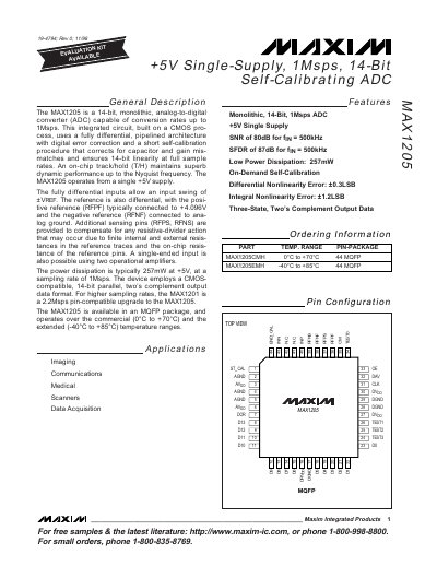
The MAX1205 is a monolithic 14‑bit analog‑to‑digital converter that operates from a single +5 V supply and supports conversion rates up to 1 Msps. It uses a fully differential, pipelined architecture with digital error correction and an on‑chip self‑calibration routine that ensures 14‑bit linearity.
The document provides detailed electrical characteristics, pin descriptions, reference‑input requirements, calibration procedure, and typical performance graphs. It also includes application notes for imaging, communications, and data‑acquisition systems.
| Supply voltage | +5 V single supply |
|---|---|
| Resolution | 14 bit |
| Maximum sampling rate | 1 Msps |
| Power dissipation | 257 mW at +5 V, 1 Msps |
| Input voltage range (differential) | ±VREF |
| Reference voltage (positive) | 4.096 V (typical) |
| Operating temperature range | -40 °C to +85 °C |
| Digital output format | Two’s complement |
| Digital output load | ≤20 pF |
The MAX1205 operates from a single +5 V supply.
Self‑calibration is initiated by asserting the ST_CAL pin high for at least four clock cycles.
Typical power dissipation is 257 mW at +5 V and a 1 Msps sampling rate.
The positive reference (RFPF) is typically set to 4.096 V.