
The document is the product manual of Vishay Dale's NTC Thermistors,Coated, introducing the product features and characteristics.
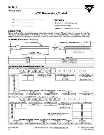
This leaflet describes Vishay's coated NTC thermistors (models M, C, and T) intended for standard PCB mounting or probe assembly. The coating is a baked‑on phenolic for durability, with models M and C using tinned solid copper leads and model T using solid nickel wires with Teflon® insulation.
The document provides detailed specifications such as body diameter, lead wire sizes, resistance ranges, dissipation constants, thermal time constants, and tolerance options (curve tracking and point match). It also includes global part numbers, curve codes, and a spreadsheet tool for calculating beta, Steinhart‑Hart constants, and total resistance tolerance.
| Lead wire size – Type M | AWG 30 (0.0100 in / 0.254 mm) |
|---|---|
| Lead wire size – Type C | AWG 28 (0.0126 in / 0.320 mm) |
| Lead wire size – Type T | AWG 30 (0.0100 in / 0.254 mm) |
| Thermal time constant (1 kΩ) | 6‑14 seconds |
| Standard point‑match tolerance | +5 % or +10 % |
Models M and C have tinned solid copper leads.
Model T uses solid nickel wires with Teflon® insulation.
Add the appropriate suffix (e.g., -B3, -A2) to the part number to specify the tolerance code.
Codes include A3, B3, C3, A2, B2, C2, A4, B4, C4, etc., as shown in the tolerance table.