
This document introduces the self-programming ability of Microchip's Enhanced FLASH Microcontroller devices
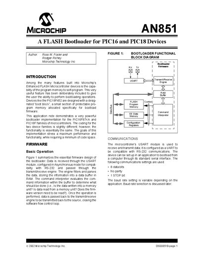
The AN851 application note explains Microchip's flash bootloader for PIC16 and PIC18 devices. It details how the boot block in program memory is used, the communication protocol over USART, and the command set that enables reading, writing, and erasing memory.
The document provides implementation guidance, including buffer limits, packet format, control‑character handling, and example software tools for programming the devices. It also covers configuration‑bit access, boot‑mode entry and exit, and debugging considerations.
| Receive/Transmit Buffer size | 255 bytes |
|---|---|
| Maximum packet length | 255 bytes |
| PIC18 boot block size | 512 bytes |
| PIC16 boot block size | 256 words |
| PIC18 write block size | 8 bytes |
| PIC18 erase block size | 64 bytes |
| PIC16 write block size | 8 bytes (4 words) |
| Default baud rate | 9600 bps |
| UART data format | 8 data bits, No parity, 1 stop bit |
| Boot mode flag value | FFh indicates boot mode |
The bootloader supports packets up to 255 data bytes, limited by the 255‑byte receive/transmit buffer.
Boot mode is entered when the last data‑memory location contains FFh; writing any other value and resetting the device exits boot mode.
The bootloader uses the USART configured for 8 data bits, no parity, 1 stop bit, typically at 9600 bps.
The bootloader inserts a DLE before any control character in the data field (byte stuffing) and does not include control characters in the checksum.