
The TPS65150 is a power management chip for TFT LCD displays. It supports a wide input voltage range of 1.8V-6V, and has an internal 2A MOSFET switch. It supports both positive and negative output voltages, and the output voltage accuracy is <1%.
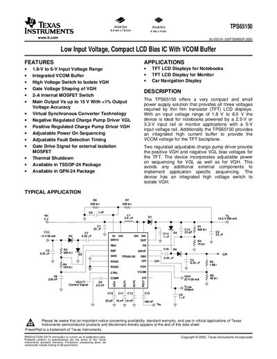
The TPS65150 provides a compact power‑supply solution for TFT LCD displays, delivering the three voltages required for thin‑film transistor panels. It operates from an input range of 1.8 V to 6 V and integrates a high‑current VCOM buffer, a high‑voltage switch for VGH isolation, and adjustable power‑on sequencing for both VGL and VGH.
The device is offered in TSSOP‑24 and QFN‑24 packages and includes extensive protection features such as thermal shutdown, adjustable fault‑detection timing, and an internal shutdown latch. Detailed electrical characteristics, pin assignments, and layout guidelines are provided for designers.
| Input voltage range | 1.8 V to 6 V |
|---|---|
| Main output voltage (Vs) | up to 15 V |
| Package options | TSSOP‑24, QFN‑24 |
| Operating ambient temperature (recommended) | -40 °C to 85 °C |
| Power dissipation (TSSOP‑24) | 3.3 W |
The device operates from 1.8 V up to 6 V input voltage.
It is offered in a 24‑lead TSSOP package (PWP) and a 24‑lead QFN package (RGE).
By connecting capacitors to the ADJ, DLY1, and DLY2 pins you can set the fall time of VGH and the delay times for VGL and VGH during startup.