
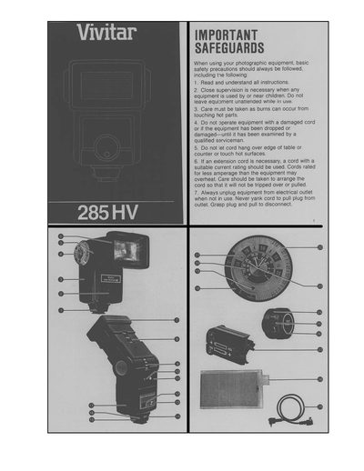
This manual begins with important safety safeguards for using the flash, including proper handling of cords, battery replacement, and avoiding water exposure. It then describes the flash unit’s components, such as the open‑flash button, sensor socket, zoom/bounce head, and various dials.
The guide explains the multiple power sources (four AA alkaline batteries, Ni‑Cad packs, HVP‑7 high‑voltage pack, PPG‑1 pistol‑grip pack, and SB‑4 AC adapter), the battery‑saving circuit, capacitor forming procedure, and how to attach the flash to a camera. Detailed sections cover automatic and manual operation, the Ready Light indicators, zoom positions, mode selector settings, and shooting techniques for on‑camera direct and bounce flash.
| Standard Power Source | Four 1.5 V AA alkaline batteries |
|---|---|
| Optional High‑Voltage Battery Pack | HVP‑7 pack (disposable or rechargeable RB‑510) |
| Optional Power Pistol Grip | PPG‑1 grip, uses AA, NiCads or NC‑3 pack |
| Optional AC Adapter | SB‑4 AC adapter for standard outlets |
| Ready Light Indication | Red at 1/2 power, green at 3/4 power, blinking red/green at full power |
| Variable Power Settings | Full, 1/2, 1/4, 1/16 power via Made Selector Dial |
It uses four 1.5 V AA alkaline batteries as the standard power source.
The Ready Light glows red at half power, green at three‑quarters power, and blinks red‑green when the battery‑saving circuit is active at full power.