
This document describes the features and characteristics of the 27 3 dB 90° Card Couplers HD-M Series, including high performance, power uniform distribution and 90° phase difference type, miniature and lightweight design, and high power capability.
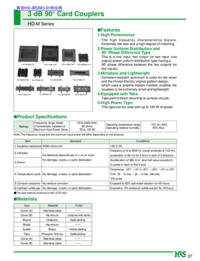
The HD‑M Series directional couplers provide high‑frequency performance with extremely low loss and a 90° phase difference between ports. They are built with a corrosion‑resistant aluminum cover and a stripline triplate design, making them miniature and lightweight while supporting up to 100 W of power.
Mounting options include three screw‑mount methods for surface‑mount circuits, with detailed guidelines for different micro‑strip board thicknesses. The datasheet also lists external dimensions, PCB mounting patterns, and environmental test results such as vibration, shock, temperature cycling, and corrosion resistance.
| Frequency range | 30 to 6400 MHz |
|---|---|
| Characteristic impedance | 50 Ω |
| Maximum input power | 50 to 100 W |
| Insulation resistance | ≥ 500 MΩ at 100 V DC |
| Operating temperature range | -10 °C to +65 °C |
| Maximum relative humidity | 95 % max |
There is a 90° phase difference between the output and the coupling.
The characteristic impedance is 50 Ω.
The coupler can be used with up to 100 W of power.
Three screw‑mount methods are described, using M2 screws tightened to 1.5 kg‑cm, with guidelines for different micro‑strip board thicknesses.