
AD9517-0 is a 12-output clock generator with integrated 2.8 GHz VCO. It features low phase noise, automatic switchover modes, and programmable delays.
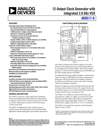
The AD9517-0 is a 12‑output clock generator with an integrated 2.8 GHz VCO. It offers low phase‑noise PLL operation, selectable LVPECL, LVDS, and CMOS outputs, and supports external VCO/VCXO up to 2.4 GHz. The device includes programmable delays, automatic reference switchover, and can operate from a single 3.3 V supply.
The datasheet provides detailed electrical specifications, pin configurations, timing characteristics, and recommended application circuits. It also lists ordering information for the 48‑lead LFCSP package and outlines the device's industrial temperature range of –40 °C to +85 °C.
| LVPECL output maximum frequency | 2950 MHz |
|---|---|
| LVDS output frequency | 800 MHz |
| CMOS output frequency | 250 MHz |
| Supply voltage (Vs) typical | 3.3 V |
| Operating temperature range | –40 °C to +85 °C |
The on‑chip VCO tunes from 2.55 GHz to 2.95 GHz.
The external VCO can be powered by connecting the charge‑pump supply (VCP) to 5 V.