
This application note introduces the features of the DD-32645C-2A OLED display module, including the EVK board schematic, symbol definition, timing characteristics, connection between OLED and EVK, and how to use the DD-32645C-2A.
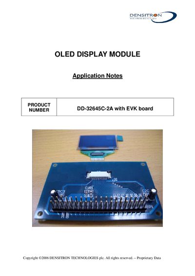
This document provides technical information for the Densitron DD-32645C-2A OLED display module used together with the evaluation (EVK) board. It includes the EVK schematic, pin symbol definitions, 8080‑parallel interface timing characteristics, and wiring details.
Key sections describe how to connect the module to the EVK, recommended initial initialization code, and detailed pin functions for data, command, control, and power signals. The timing table lists voltage ranges, temperature limits, and signal timing parameters needed for proper operation.
| Supply voltage (VDD) | 2.4 to 3.5 V |
|---|---|
| Operating temperature (TA) | -40 to 85 °C |
| Clock Cycle Time | 300 ns |
| Address Setup Time | 0 ns |
| Address Hold Time | 0 ns |
| Write Data Setup Time | 40 ns |
| Write Data Hold Time | 15 ns |
| Read Data Hold Time | 20 ns |
| Output Disable Time | 70 ns |
| Access Time | 140 ns |
| Chip Select Low Pulse Width (read) | 20 ns |
| Chip Select Low Pulse Width (write) | 60 ns |
| Chip Select High Pulse Width (read) | 60 ns |
| Chip Select High Pulse Width (write) | 60 ns |
| Rise Time | 15 ns |
| Fall Time | 15 ns |
The module operates with a VDD of 2.4 V to 3.5 V.
The module is placed into the connector on the top side of the EVK PCB and secured with a screw; the connection pads are on the top side.