
This is a product catalog, including 99.01, 99.02, 99.80 and other models of sockets and switches
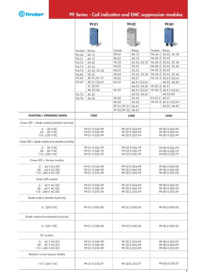
This manual describes the operation of the Finder 99 Series coil‑indication and EMC‑suppression modules. It covers the voltage‑current characteristics when switching resistive loads and relay coils, explains the inductive voltage spikes that occur on de‑energisation, and provides guidance on selecting appropriate suppression devices.
Various module types are presented, including green LED‑diode, green LED‑varistor, RC, and residual‑current bypass modules. The document details their operating voltage ranges, polarity requirements, and the effect of each module on coil release time and voltage‑spike mitigation.
| Green LED + diode module (standard polarity) operating voltage | 6‑24 VDC |
|---|---|
| Green LED + varistor module operating voltage | 6‑24 VDC |
| RC module operating voltage | 6‑24 V AC/DC |
Yes, the LED indicator lights up whenever the coil is energized.
Using a varistor results in an insignificant increase in the relay release time.