
The MAX525 combines four low-power, voltage-output, 12-bit digital-to-analog converters (DACs) and four precision output amplifiers in a space-saving, 20-pin package. In addition to the four voltage outputs, each amplifier’s negative input is also available to the user. This facilitates specific gain configurations, remote sensing, and high output drive capacity, making the MAX525 ideal for industrial-process-control applications. Other features include software shutdown, hardware shutdown lockout, an active-low reset which clears all registers and DACs to zero, a user-programmable logic output, and a serial-data output. Each DAC has a double-buffered input organized as an input register followed by a DAC register. A 16-bit serial word loads data into each input/DAC register. The serial interface is compatible with SPI™/QSPI™ and MICROWIRE™. It allows the input and DAC registers to be updated independently or simultaneously with a single software command. The DAC registers can be simultaneously updated through the 3-wire serial interface. All logic inputs are TTL/CMOS-logic compatible.
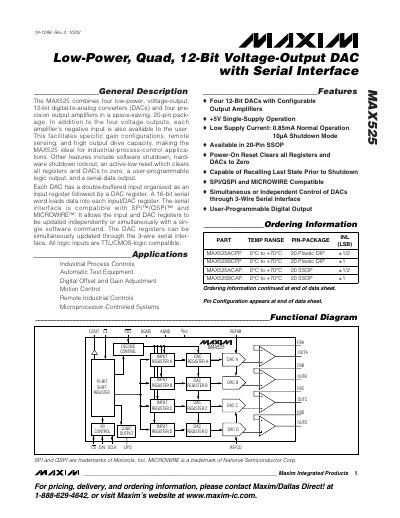
The Maxim MAX525 combines four low‑power 12‑bit DACs and four precision output amplifiers in a compact 20‑pin package. Each amplifier’s negative input is available for gain configuration, remote sensing, and high‑drive applications, making it suitable for industrial process control, test equipment, and motion control.
Key features include +5 V single‑supply operation, a typical supply current of 0.85 mA (10 µA in shutdown), SPI/QSPI and MICROWIRE compatible serial interface, user‑programmable logic output, and a shutdown lockout pin. The device offers both unipolar and bipolar output configurations, with typical settling time of 12 µs and a slew rate of 0.6 V/µs.
| Resolution | 12‑bit |
|---|---|
| Supply Voltage | +5 V ±10 % |
| Normal Supply Current | 0.85 mA |
| Shutdown Supply Current | 10 µA |
| Maximum Clock Frequency | 10 MHz |
| Typical Slew Rate | 0.6 V/µs |
| Typical Settling Time | 12 µs (±½ LSB) |
The MAX525 draws approximately 0.85 mA at a +5 V supply.
The serial interface can operate up to 10 MHz.