
The MAX8553/MAX8554 are Maxim’s synchronous step-down controllers for DDR memory power management. The MAX8553 generates 1/2 VREFIN voltage for VTT and VTTR. The VTT and VTTR tracking voltages are maintained within 1% of 1/2 VREFIN. The MAX8554 is a 4.5V to 28V input voltage, nontracking step-down controller with a low 0.6V feedback threshold voltage. The MAX8553/MAX8554 use Maxim’s proprietary Quick-PWM™ architecture for fast transient response and operate with selectable pseudo-fixed frequencies. Both controllers can operate without an external bias supply. The controllers operate in synchronous-rectification mode to ensure balanced current sourcing and sinking capacity of up to 25A. The MAX8553/MAX8554 also provide up to 95% efficiency, making them ideal for server and point-of-load applications. Additionally, a low 5µA shutdown current allows for longer battery life in notebook applications. Lossless current monitoring is achieved by monitoring the low-side MOSFET’s drain-to-source voltage. The MAX8553/MAX8554 have an adjustable foldback current limit to withstand a continuous output overload and short circuit. Digital soft-start provides control of inrush current during power-up. Overvoltage protection shuts the converter down and discharges the output capacitor. The MAX8553/MAX8554 come in space-saving 16-pin QSOP packages.
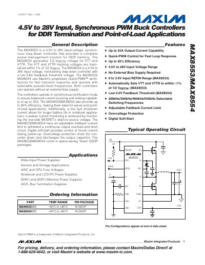
The MAX8553 and MAX8554 are 4.5 V to 28 V input‑voltage synchronous buck controllers designed for DDR memory termination and point‑of‑load applications. Both devices use Maxim’s Quick‑PWM architecture for fast transient response, operate without an external bias supply, and can deliver up to 25 A of balanced source and sink current.
The datasheet provides detailed electrical characteristics, absolute maximum ratings, typical operating curves, and design guidelines such as MOSFET selection, droop‑resistor sizing, and power‑dissipation calculations. The devices are offered in a space‑saving 16‑pin QSOP package and support selectable switching frequencies of 200 kHz, 300 kHz, 400 kHz or 550 kHz.
| Input Voltage Range (VL connected to V+) | 4.5 V – 5.5 V |
|---|---|
| Maximum Output Current Capability | 25 A |
| Efficiency | up to 95 % |
| Shutdown Supply Current | 5 µA |
| Selectable Switching Frequencies | 200 kHz, 300 kHz, 400 kHz, 550 kHz |
| Package | 16‑pin QSOP |
The input voltage range is 4.5 V to 5.5 V.
They can source or sink up to 25 A of current.
The shutdown supply current is 5 µA.
Both devices are available in a 16‑pin QSOP package.