
ISL6620, ISL6620A is a high frequency MOSFET driver designed by Intersil for VR11.1 controller to drive upper and lower power N-Channel MOSFETs in a synchronous rectified buck converter topology. It has advanced PWM protocol and can work with Intersil VR11.1 controller. When ISL6620, ISL6620A detects a PSI protocol sent by an Intersil VR11.1 controller, it activates Diode Emulation (DE) operation; otherwise, it operates in normal Continuous Conduction Mode (CCM) PWM mode. The IC is biased by a single low voltage supply (5V), minimizing driving losses in high MOSFET gate capacitance and high switching frequency applications. Each driver is capable of driving a 3nF load with less than 10ns rise/fall time. Bootstrapping of the upper gate driver is implemented via an internal low forward drop diode, reducing implementation cost, complexity, and allowing the use of higher performance, cost effective N-Channel MOSFETs. To further improve efficiency and reduce cost, ISL6620, ISL6620A adopts single power supply, high switching frequency, high gate drive current and enhanced EMI suppression technologies.
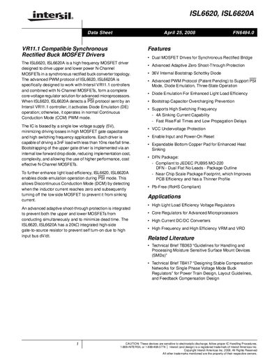
The ISL6620 and ISL6620A are high‑frequency MOSFET drivers designed for synchronous rectified buck converter topologies. They operate from a single 5 V supply and feature advanced PWM protocols, diode‑emulation mode, and adaptive shoot‑through protection.
The document includes ordering information, pin‑out diagrams, absolute maximum ratings, recommended operating conditions, detailed electrical specifications, and layout guidelines to help designers integrate the driver into voltage regulator and DC‑DC converter designs.