
ISL6594A and ISL6594B are high frequency MOSFET drivers specifically designed to drive upper and lower power N-Channel MOSFETs in a synchronous rectified buck converter topology.
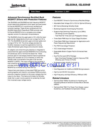
The ISL6594A and ISL6594B drivers are designed to drive upper and lower N‑Channel MOSFETs in a synchronous‑rectified buck converter topology. They provide dual MOSFET drives, adjustable gate‑voltage ranges and a three‑state PWM input for flexible power‑sequencing.
Key features include adaptive zero shoot‑through protection, over‑voltage and under‑voltage safeguards, a 36 V internal bootstrap Schottky diode, and support for switching frequencies up to 2 MHz. The devices are offered in 8‑lead SOIC and 3 × 3 mm DFN packages for compact PCB layouts.
| Adjustable Gate Voltage Range | 5 V to 12 V (lower gate), 12 V fixed (upper gate on ISL6594A) |
|---|---|
| Maximum Switching Frequency | up to 2 MHz |
| Dual MOSFET Drives | Provides separate upper and lower gate drives |
| Internal Bootstrap Diode Voltage | 36 V |
| VCC Rising Threshold | 9.35 V typ, 10.0 V max |
The ISL6594A drives the upper gate at a fixed 12 V, while the lower gate can be set anywhere between 5 V and 12 V.
An adaptive zero shoot‑through protection monitors the gate voltages and disables the drivers if both upper and lower MOSFETs try to conduct at the same time.
The VCC rising threshold is typically around 9.35 V (up to 10.0 V max) and the falling threshold is about 7.35 V (up to 8.0 V max).