
The ISL6614B is a dual advanced synchronous rectified Buck MOSFET driver with pre-power-on overvoltage protection. It is designed to drive two channel MOSFETs in a synchronous rectified Buck converter topology. This driver, combined with HIP63xx or ISL65xx multi-phase Buck PWM controllers and N-Channel MOSFETs, provides complete core-voltage regulator solutions for advanced microprocessors. The ISL6614B features a 7V rising threshold and drives both the upper and lower gates simultaneously over a range from 5V to 12V. This drive voltage provides the flexibility necessary to optimize applications involving trade-offs between gate charge and conduction losses. The driver is optimized for POL DC/DC converters for IBA systems. It integrates advanced adaptive zero shoot-through protection to prevent both the upper and lower MOSFETs from conducting simultaneously and minimize dead time. These products also have an overvoltage protection feature that operates before VCC exceeds its turn-on threshold, at which point the PHASE node is connected to the gate of the low-side MOSFET (LGATE).
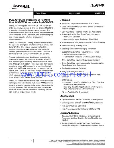
The ISL6614B integrates two MOSFET drivers designed for synchronous‑rectified buck converters. It features a 7 V rising threshold, adjustable gate‑drive voltage (5 V‑12 V), and advanced adaptive zero‑shoot‑through protection to prevent simultaneous conduction of the upper and lower MOSFETs.
The device supports high‑frequency operation up to 1 MHz, includes a three‑state PWM input with shutdown window, and offers pre‑POR overvoltage protection. It is supplied in SOIC‑14 and QFN‑16 packages, both RoHS‑compliant and Pb‑free.
| VCC Rising Threshold (typical) | 7 V |
|---|---|
| Maximum Switching Frequency | 1 MHz |
| Maximum Junction Temperature | +150 °C |
| Operating Temperature Range | -40 °C to +85 °C |
The typical VCC rising threshold is 7 V.
A pre‑POR overvoltage protection function is activated during initial startup.
The driver supports switching frequencies up to 1 MHz.