
ISL6610, ISL6610A Dual Synchronous Rectified MOSFET Drivers
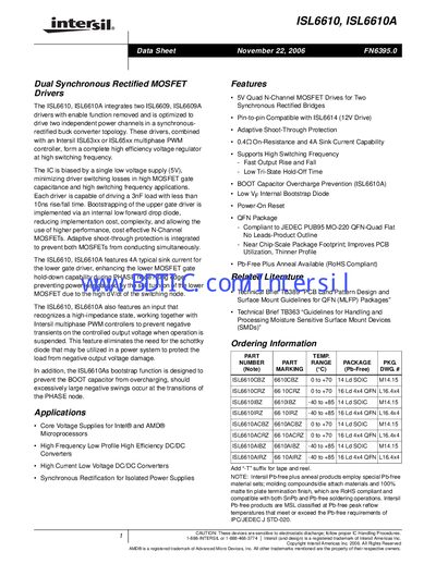
The ISL6610 and ISL6610A are dual synchronous rectified MOSFET drivers designed to drive two independent power channels in a buck‑converter topology. They operate from a single 5 V supply and provide fast 10 ns rise/fall times, adaptive shoot‑through protection, and bootstrap‑capacitor over‑charge prevention.
Key features include 4 A typical sink current for the lower gate driver, 0.4 Ω on‑resistance, and compatibility with high‑frequency, low‑profile DC‑DC converters. The devices are offered in 14‑lead SOIC and 16‑lead QFN packages and are RoHS‑compliant. Recommended operating ambient temperature is –40 °C to +85 °C, with an absolute maximum of –40 °C to +125 °C.
| Ambient Temperature Range (Absolute Max) | -40 °C to +125 °C |
|---|---|
| Ambient Temperature Range (Recommended) | -40 °C to +85 °C |
| Typical Sink Current (Lower Gate) | 4 A |
| On‑Resistance (Lower Gate) | 0.4 Ω |
| Package Types | 14‑lead SOIC, 16‑lead QFN |
The lower gate driver can sink up to 4 A typical current.
The device is recommended to operate between –40 °C and +85 °C.
It is offered in a 14‑lead SOIC package and a 16‑lead QFN package.
The circuitry monitors the LGATE voltage and, after a short delay, turns on the upper gate to prevent both MOSFETs from conducting simultaneously.