
The HI-574A, HI-674A are complete 12-bit Analog-to-Digital Converters with a digital interface for microprocessor control, a +10V reference clock, three-state outputs, and successive approximation conversion performed by two monolithic dice. The analog die features the Intersil Dielectric Isolation process for enhanced AC performance and freedom from latch-up. Custom design of each IC (bipolar analog and CMOS digital) has resulted in improved performance compared to previous versions. The voltage comparator has high PSRR and a high-speed current-mode latch, providing precise decisions down to 0.1 LSB of input overdrive. Noise reduction of more than 2X has been achieved by using current instead of voltage for signal transmission between the analog and digital ICs. The clock oscillator is current controlled for excellent temperature stability. The HI-X74(A) offers standard unipolar and bipolar input ranges, with laser trimming for specified linearity, gain, and offset accuracy. The low noise buried zener reference circuit is trimmed for minimum temperature coefficient.
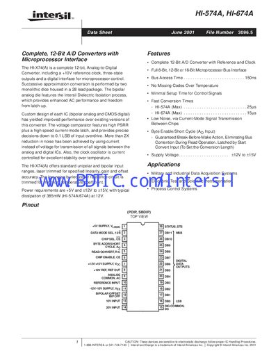
The HI‑574A and HI‑674A are complete 12‑bit analog‑to‑digital converters with integrated reference, clock, and microprocessor‑compatible digital interface. They offer both unipolar and bipolar input ranges and feature low‑noise, current‑mode signal transmission.
The document lists detailed electrical specifications, timing diagrams, pin descriptions, and mechanical package dimensions for the 28‑lead PDIP and SBDIP versions, along with ordering numbers and absolute maximum ratings for safe operation.
| Resolution | 12‑bit |
|---|---|
| Supply Voltage | +5V and +12V to +15V |
| Package | 28‑lead PDIP or SBDIP |
| Logic Input High Level | +2.4 V to +5.5 V |
The devices operate from a +5 V logic supply and a +12 V to +15 V analog supply.
Both devices are offered in a 28‑lead dual‑in‑line package (PDIP or SBDIP).
Pin 7 provides the positive supply voltage (+12 V/+15 V) for the analog section.