
The document introduces the features and characteristics of a Rev. 4126L-CAN-01/08 product. The product adopts the 80C51 core architecture and has 256 bytes of on-chip RAM and 256 bytes of on-chip XRAM. It also has 16K bytes of on-chip flash memory with 10 years of data retention and 100K erase/write cycles, as well as a boot code section with independent lock bits. In addition, the product has 2K bytes of on-chip flash for a bootloader and supports in-system programming by on-chip boot program (CAN, UART) and IAP capability. It also features 2K bytes of on-chip EEPROM with 100K erase/write cycles, 14 sources 4-level interrupts, three 16-bit timers/counters, a full duplex UART compatible with 80C51, a maximum crystal frequency of 40 MHz, double data pointer, 21-bit watchdog timer, a 10-bit resolution analog-to-digital converter (ADC) with 8 multiplexed inputs, and a full CAN controller that is fully compliant with CAN rev.# 2.0A and 2.0B.
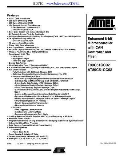
The AT89C51CC02 is a low‑pin‑count 8‑bit Flash microcontroller that integrates a full CAN controller, 16 KB of on‑chip Flash, 256 B RAM, 256 B XRAM, 2 KB EEPROM, and a 10‑bit ADC with eight multiplexed inputs. It supports In‑System Programming, a bootloader section, and a range of power‑saving modes.
The document lists detailed pin configurations, port structures, read‑modify‑write instructions, absolute maximum ratings, and ordering information for the available SOIC28, SOIC24, PLCC28, and VQFP32 packages.
| Core Architecture | 80C51 |
|---|---|
| Flash Memory | 16 KB |
| RAM | 256 B |
| XRAM | 256 B |
| EEPROM | 2 KB |
| ADC Resolution | 10‑bit |
| ADC Channels | 8 |
| CAN Compatibility | CAN 2.0A/B |
| Maximum Clock Frequency | 40 MHz |
| Power Supply Voltage | 3 V – 5.5 V |
| Operating Temperature | -40 °C to +85 °C |
| Package Types | SOIC28, SOIC24, PLCC28, VQFP32 |
The device supports up to 1 Mbit/s at an 8 MHz crystal frequency.
It provides eight analog input channels via the 10‑bit ADC.
It operates from 3 V to 5.5 V.
It is available in SOIC28, SOIC24, PLCC28, and VQFP32 packages.