
This document describes the features and characteristics of a product, including core architecture, on-chip RAM and XRAM capacity, flash memory, boot code section, bootloader, in-system programming capabilities, EEPROM, interrupts, timers/counters, UART compatibility, digital I/O lines, PCA, double data pointer, watchdog timer, ADC, and full CAN controller.
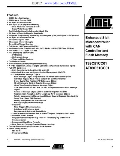
The AT89C51CC01 is an 8‑bit microcontroller with an integrated CAN controller, designed for automotive and industrial network applications. It combines a 32 KB Flash memory, 256 B RAM, 1 KB XRAM, and a 2 KB EEPROM, offering in‑system programming via UART or CAN.
The document includes feature highlights, pin‑out tables, port and SFR descriptions, timing and power specifications, package options, and absolute maximum ratings, enabling designers to integrate the device into their systems.
| Core Architecture | 80C51 |
|---|---|
| On‑chip RAM | 256 Bytes |
| On‑chip XRAM | 1 KB |
| Flash Memory | 32 KB |
| Data Retention | 10 Years at 85 °C |
| Erase/Write Cycle | 100 K cycles |
| Boot Flash | 2 KB |
| EEPROM | 2 KB |
| Interrupt Sources | 14 sources, 4‑level |
| Timers/Counters | Three 16‑bit |
| UART | Full‑duplex 8051 compatible |
| Maximum Crystal Frequency | 40 MHz (X2 mode), 20 MHz core |
| Ports | Five ports (32 + 2 I/O lines) |
| PWM | 8‑bit, five‑channel 16‑bit PCA |
| ADC | 10‑bit, 8 multiplexed inputs |
| Maximum CAN Transfer Rate | 1 Mbit/s at 8 MHz crystal |
| Supply Voltage | 3 V to 5.5 V |
| Operating Temperature | -40 °C to +85 °C |
| Package Options | VQFP44, PLCC44 |
The device operates from 3 V to 5.5 V.
It is rated for –40 °C to +85 °C.
The microcontroller provides 15 independent CAN message objects.
Up to 1 Mbit/s when using an 8 MHz crystal.