
This data sheet introduces the features and characteristics of the 80C52X2-24I/P-QFN-34 microcontroller.
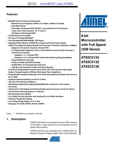
This manual describes the AT83C5134/35/36 family of 8‑bit microcontrollers based on the 80C52X2 core. It lists key features such as a maximum core frequency of 48 MHz (X1 mode) or 24 MHz (X2 mode), dual data pointer, full‑duplex enhanced UART, three 16‑bit timers, on‑chip ROM/EEPROM, expanded RAM, and a USB 2.0 full‑speed module with multiple endpoints.
The document includes block diagrams, detailed pin‑out tables for various packages (QFN32, MLF48, TQFP64), signal descriptions for keypad, PCA, serial I/O, timers, LEDs, TWI, SPI and ports, as well as chapters on USB controller operation, power‑management modes, watchdog timer, reset behavior, electrical characteristics, ordering and packaging information, and revision history.
| Core | 80C52X2 (6 clocks per instruction) |
|---|---|
| Maximum Core Frequency | 48 MHz (X1 mode), 24 MHz (X2 mode) |
| On‑chip ROM | 8 KB / 16 KB / 32 KB |
| Expanded RAM (ERAM) | 1024 Bytes |
| Timer/Counters | Three 16‑bit timers (T0, T1, T2) |
| LED Outputs | 4 direct‑drive LED outputs, 2‑6‑10 mA programmable current |
| Supply Voltage | 2.7 V to 3.6 V |
| Package Options | QFN32, MLF48, TQFP64 |
The device provides four direct‑drive LED outputs with programmable current sources (2 mA, 6 mA, or 10 mA).
The AT83C5134/35/36 operates from 2.7 V to 3.6 V.
It has three 16‑bit timer/counters named T0, T1, and T2.