
This document introduces the features of the ADATE304 product, including the driver, comparator, PMU, voltage range, pulse width, current range, DAC, HVOUT output buffer, package, power consumption, etc.
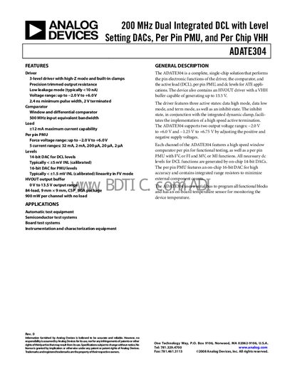
The ADATE304 is a dual‑integrated DCL (driver, comparator, active load, per‑pin PMU and level DACs) designed for automatic test equipment and semiconductor test systems. It includes a high‑speed driver with three active states, a window and differential comparator, and an HVOUT buffer capable of up to 13.5 V output.
The device is programmed via a Serial Peripheral Interface (SPI) and provides on‑chip 14‑bit DACs for DCL levels and 16‑bit DACs for PMU levels. It is offered in an 84‑lead CSP‑BGA package (9 mm × 9 mm) and operates over a voltage range of –2.0 V to +6.0 V (or –1.25 V to +6.75 V).
| Voltage range | –2.0 V to +6.0 V |
|---|---|
| Maximum output current | +12 mA |
| Per‑pin PMU current ranges | 32 mA, 2 mA, 200 pA, 20 pA, 2 pA |
| DCL level DAC resolution | 14‑bit |
| PMU level DAC resolution | 16‑bit |
| HVOUT output buffer range | up to 13.5 V |
| Package | 84‑lead CSP‑BGA, 9 mm × 9 mm |
The ADATE304 supports an output voltage range from –2.0 V to +6.0 V (and an alternative range of –1.25 V to +6.75 V).
The ADATE304 is a dual‑integrated DCL, providing two independent channels.
The device can source up to +12 mA of output current.
All functional blocks are programmed via a Serial Peripheral Interface (SPI).