
MAX780 Dual-Slot PCMCIA Analog Power Controller is a product launched by Maxim Integrated Products. It provides the power switching and status signals necessary to control two Personal Computer Memory Card International Association (PCMCIA) Release 2.0 card slots.
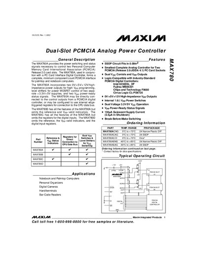
This manual describes the MAX780 family of dual‑slot PCMCIA analog power controllers. It covers the device’s functional blocks, power‑switching capabilities, and the logic‑compatible interface options for Intel, Fujitsu, Chips and Technology, and Cirrus Logic PCMCIA digital controllers.
The document provides absolute maximum ratings, detailed electrical characteristics, pin descriptions, control‑logic tables, and application information such as Vpp switching, Voc switching, and mechanical or MOSFET‑based interlock solutions. Package dimensions and ordering information for the various A‑D variants are also included.
| VCCIN Input Voltage Range | 2.85 V – 5.5 V |
|---|---|
| VPPIN Input Voltage Range | 0 V – 12.6 V |
| Quiescent Supply Current (normal mode) | 130 µA |
| Reference Voltage Output (MAX780A/C) | 1.25 V |
| Package Type (MAX780A/B) | 24‑pin Narrow Plastic DIP |
VCCIN may be supplied between 2.85 V and 5.5 V, while VPPIN may be supplied from 0 V up to 12.6 V.
A bypass capacitor on the VPPIN line should be at least ten times larger than the capacitance of the AVPP or BVPP lines to ground, e.g., 1 µF when the line capacitance is 0.1 µF.
The AGPI and BGPI pins are logic‑level status outputs that go low when AVPP or BVPP exceed 11.05 V, respectively.
Pulling the SHDN pin low puts the device into a low‑current state, disabling the reference and the AGPI/BGPI status outputs while keeping Vpp switching functional.