
TB6569FG is a full-bridge driver IC for DC motor drive that adopts MOS structure for the output transistors. It features low ON resistance, PWM driving method, and high thermal efficiency. It can select four modes of forward/reverse/short brake/stop by two input signals, IN1 and IN2. Important points to note include power supply voltage range, output current limitation, control inputs, and PWM frequency.
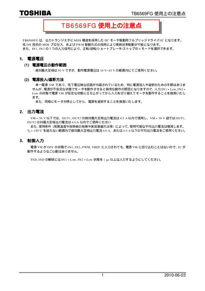
The Toshiba TB6569FG is a full‑bridge driver IC for DC motor control that uses a MOS‑structure output transistor. It supports four operation modes (forward, reverse, short‑brake, stop) via two input signals and offers PWM speed control.
The manual provides recommended supply voltage ranges, output current limits, PWM frequency guidelines, recommended external components, and safety precautions such as over‑current detection and thermal design. This manual is written in Japanese.
| Recommended operating supply voltage range | 10 V – 45 V |
|---|---|
| PWM frequency range | ≤ 100 kHz |
| Recommended pull‑up resistor for ALERT pin | 10 kΩ – 100 kΩ |
| Recommended external resistor for RSGND pin | ≥ 0.1 Ω |
| Junction‑to‑ambient thermal resistance (example) | 89.3 °C/W |
| Maximum power dissipation (example, VM=24 V, I=0.5 A) | 0.417 W |
Use a supply voltage between 10 V and 45 V.
The device supports PWM frequencies up to 100 kHz.
Connect a pull‑up resistor of 10 kΩ to 100 kΩ to the ALERT pin to obtain a High level.