
TB62209FG is a stepping motor driver produced by Toshiba. It adopts a chopper mode microstep pseudo-sine wave drive, which can support 2 phase, 1-2 (2 types), W1-2, 2W1-2, 4W1-2 phase and fixed axis mode. The maximum output current is 1.8 A, and the maximum power supply voltage is 40 V.
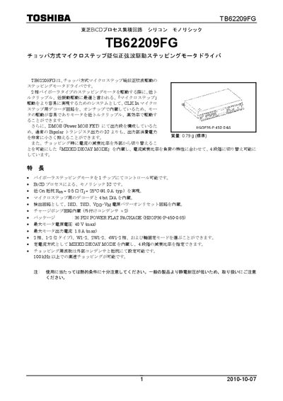
This handbook describes the TB62209FG chopper‑type microstep stepping‑motor driver, including its features such as on‑chip mixed‑decay mode, low on‑resistance MOSFET output stage, and integrated decoder and 4‑bit D/A. The document contains block diagrams, logic unit functions, current‑setting and feedback circuits, and pin‑assignment tables.
Additional sections cover equivalent input/output circuits, thermal and over‑current protection, handling precautions, and legal usage notes. The material is intended for designers and system integrators who need detailed electrical characteristics and connection details for implementing the driver in their products. This manual is written in Japanese.
| On‑resistance (Ron) | 0.5 Ω (typ.) |
|---|---|
| Package | 36‑pin Power Flat Pack (HSOP36‑P‑450‑0.65) |
| Maximum motor supply voltage | 40 V |
| Maximum motor output current | 1.8 A |
| Mass | 0.79 g |
The driver supports a maximum motor supply voltage of 40 V.
Four decay‑ratio stages can be selected via the mixed‑decay mode.
The typical on‑resistance is 0.5 Ω at 25 °C and 1 A.
The STANDBY pin has an internal ~100 kΩ pull‑down and must be connected to GND when unused to avoid malfunction.