
The Mitsubishi PM300RLA060 Intelligent Power Module datasheet provides specifications, electrical and thermal characteristics, mechanical ratings, and…
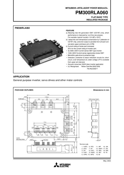
This datasheet describes the Mitsubishi PM300RLA060 flat‑base insulated‑package Intelligent Power Module. It outlines the module’s features such as a 5th‑generation IGBT (CSTBT) chip, over‑temperature protection, and high current ratings for inverter and brake parts. Application examples include general‑purpose inverters, servo drives and other motor‑control systems.
The document lists detailed electrical ratings (collector‑emitter voltage, current limits, supply voltage), thermal resistance values, mechanical dimensions and mounting torque, as well as precautions for testing and notes for stable and safe operation. Performance curves illustrate switching times, voltage‑current characteristics and transient thermal impedance for both inverter and brake sections.
| Inverter Part Current Rating | 300 A at 600 V |
|---|---|
| Brake Part Current Rating | 150 A at 600 V |
| Supply Voltage (VCC) | 300 V |
| Maximum Collector Current (IC) | 300 A |
| Thermal Resistance (junction‑to‑case, typical) | 0.12 °C/W |
| Module Dimensions | 10.56 mm (flat‑base) |
The inverter part can handle up to 300 A at 600 V.
The recommended supply voltage is 300 V.
Minimize wiring length between the opto‑coupler and the IPM input, reduce stray capacitance, and place a low‑impedance capacitor between VCC and GND for each fast‑switching opto‑coupler.