
The Analog Devices DC3230A demo manual explains setup, operation, and performance of the LTM4652‑based inverting regulator demo board.
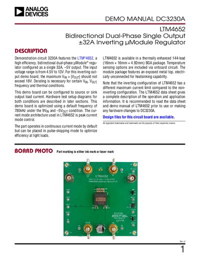
This manual provides step‑by‑step procedures for configuring the DC3230A demonstration board in both sourcing and sinking current modes. It includes wiring diagrams, jumper settings, and safety notes for proper operation.
The document also lists the complete parts bill of materials, schematic diagrams, and measured performance data such as efficiency, output voltage ripple, and thermal characteristics. Users can reference the on‑board BNC connector for ripple measurements and the level‑shift circuits for external control signals.
| Input Voltage Range | 4.5 V to 13 V |
|---|---|
| Switching Frequency (default) | 780 kHz |
| Output Current Range | –32 A to +32 A |
Connect the input power supply between VIN (J1) and GND (J3), connect the load’s positive lead to GND (J2) and the negative lead to VOUT– (J4), then power up the board.
JP2 RUN is set to ON by default.
The output voltage is typically –5.096 V ± 1 % (≈ –5.054 V to –5.15 V).
Use the onboard BNC terminal, connect a short BNC cable from VOUT– (J5) to an oscilloscope probe, and avoid using a long ground lead.