
This guide explains decoupling techniques to reduce power‑supply noise for analog and mixed‑signal ICs, covering capacitor types, layout and ferrite beads.
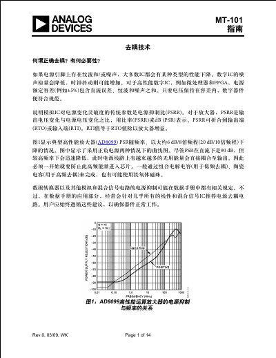
The MT‑101 guide describes why proper decoupling is essential for high‑performance analog and mixed‑signal circuits. It explains how power‑supply ripple and noise can degrade digital and analog IC performance and introduces the power‑suppression ratio (PSRR) as a key metric.
The document details the selection and placement of electrolytic, ceramic, polymer and solid‑tantalum capacitors, the use of ferrite beads, and the design of LC resonant networks. Practical examples with AD8099, AD8000 and AD9445 illustrate the impact of correct versus poor decoupling on amplifier and ADC performance. This manual is written in Chinese.
| Typical electrolytic capacitor value range | 10 µF – 100 µF |
|---|---|
| Equivalent series inductance (ESL) of a 100 µF capacitor | 1.6 nH |
| Equivalent series inductance (ESL) of a 100 µF capacitor (alternative) | 16 nH |
| Self‑resonant frequency of the capacitor | 1 Hz (example value shown) |
A large electrolytic capacitor of typically 10 µF to 100 µF should be placed no more than 2 inches from the chip to act as a local charge reservoir.