
The CN‑0399 circuit notes from Analog Devices describe a USB‑powered portable RF power meter covering 9 kHz‑6 GHz using ADL5904, AD7091R and ADP160.
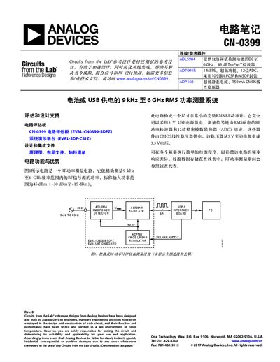
The CN‑0399 reference design provides a compact RMS RF power meter that can be powered from a 5 V USB source. It measures RF signals from 9 kHz to 6 GHz and outputs a voltage proportional to the RMS power, which is digitized by a 12‑bit ADC.
The design includes a wide‑band ADL5904 detector, a low‑power AD7091R SAR ADC, and an ADP160 CMOS linear regulator that supplies 3.3 V to the detector and ADC. Calibration data are stored in a lookup table and applied by a PC‑based GUI for real‑time power readout. This manual is written in Chinese.
| Frequency range | 9 kHz – 6 GHz |
|---|---|
| ADC resolution | 610 µV (LSB) |
| ADC power consumption | 1 mW |
| Detector power consumption | 3 mA |
| USB supply voltage | 5 V |
It measures RF signals from 9 kHz up to 6 GHz.
A three‑point calibration is run at each frequency, storing slope and intercept values in a lookup table.