
Technical data sheet for the ADuM1410/ADuM1411/ADuM1412 quad‑channel digital isolators from Analog Devices.
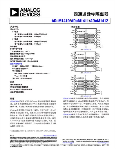
The ADuM141x family provides four independent isolation channels using Analog Devices' iCoupler® technology. The devices support 3 V‑5 V supply operation, up to 10 Mbps data rates, and feature low power consumption compared with traditional optocouplers.
The document includes detailed electrical specifications, switching characteristics, packaging information, regulatory certifications, and application guidelines for industrial and communication interfaces such as SPI, RS‑232/422/485, and isolated data converters. This manual is written in Chinese.
| Supply voltage range (5 V version) | 4.5 V – 5.5 V |
|---|---|
| Maximum data rate | 10 Mbps (NRZ) |
| Isolation voltage rating | 2500 V rms (1 min) |
| Static supply current per channel (5 V) | 1.3 mA (max, 0‑2 Mbps) |
| Input enable time | 2.0 µs |
The devices can operate up to 10 Mbps using NRZ encoding.
They are rated for 2500 V rms isolation for at least one minute.
The recommended supply voltage is between 4.5 V and 5.5 V.
The input enable time is specified as 2.0 µs.